How to Make Universal Battery Charger 4 Steps with Pictures Circuit Diagram 12V Battery Charger Circuit Useful Steps. Follow the steps on how to make a 12V Battery charger. 1) Make a Bridge rectifier by connecting 4 1N4007 Diodes in the following configuration. 2) Solder the +ve & -ve Terminals of the bridge rectifier to the secondary winding of the Non-C.T Transformer. 3) Trim excess leads of the bridge rectifier. In this video, we demonstrate how to build aIn this video, we demonstrate how to build a simple yet effective 12V battery charger circuit with an automatic c Yes, building a circuit for a homemade battery charger is a relatively simple process. You will need to obtain a few basic components such as a transformer, diodes, capacitors, and resistors. Once you have these components, you can follow a step-by-step guide to create a circuit that will charge your battery.
How to Make Lipo Battery Charger Circuit: In this project, we are going to make a simple lipo battery charger using TP4056 module with battery protection. The circuit that charges the battery by supplying the charge carrier (i.e-electrons) to it is battery charger circuit. Most of…
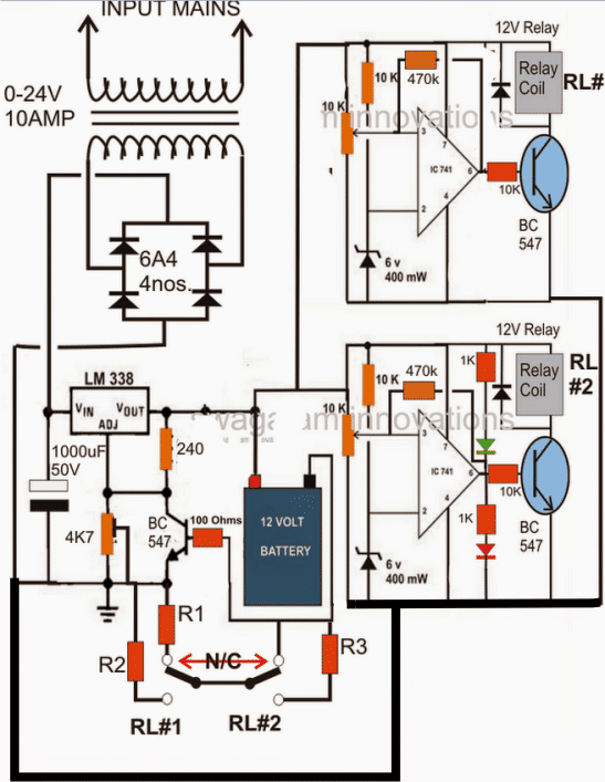
how to make battery charger control circuit Circuit Diagram
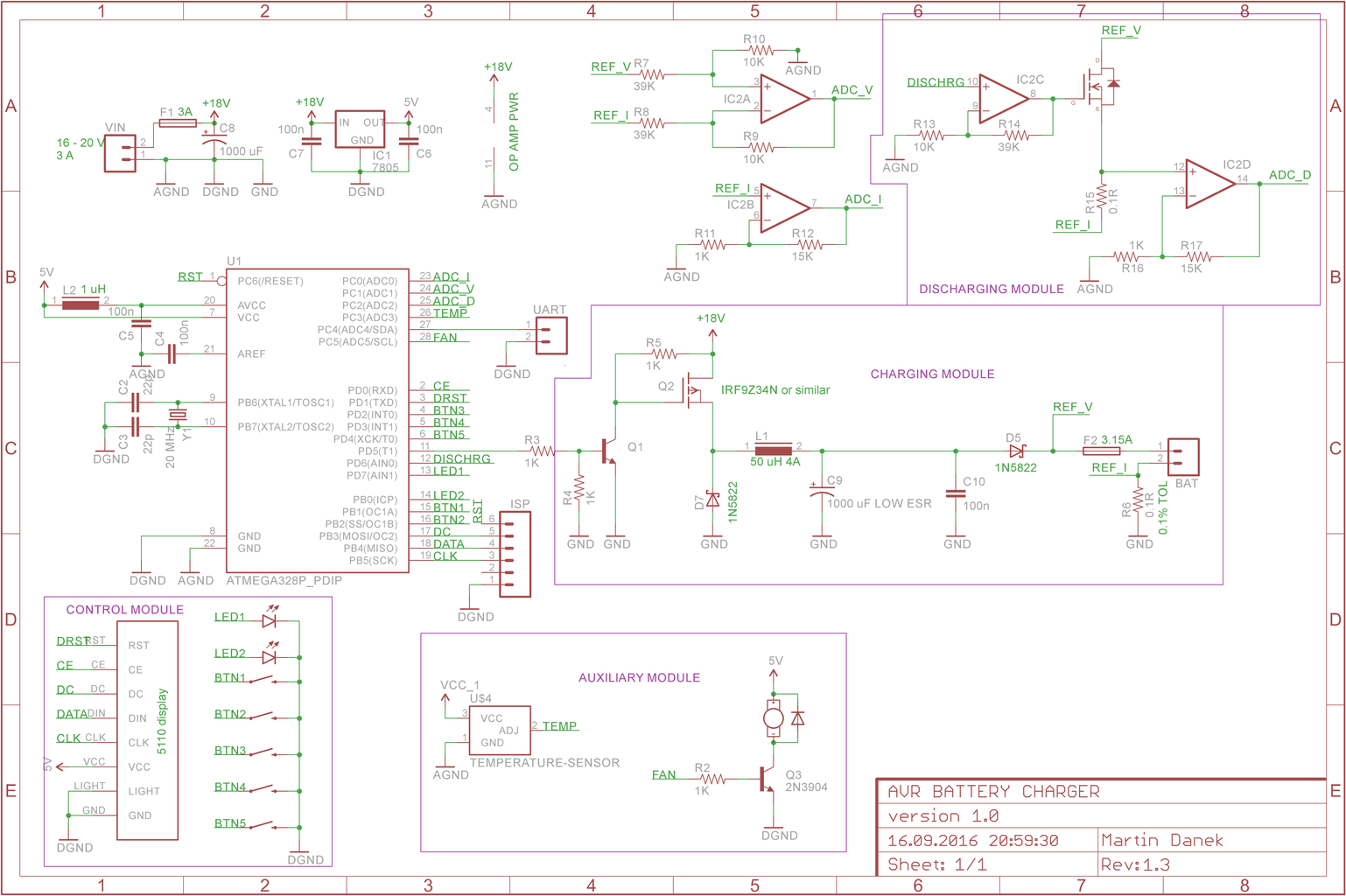
In an SLA battery charger, the cyclic rate has to be monitored as at this rate; the battery will overcharge once it has reached capacity. Charging can be done with a current limiting benchtop power supply. Just set the voltage to the value you will use and set the current limit to the value specified on the battery. It gives you all the information you need to make a high-quality battery charger from scratch. So, get ready to learn valuable insights on building your constant-current battery charger circuit and take a step towards becoming a self-sufficient electronics pro! Circuit 1: Single Resistor Method Now lets see how the entire battery charger design may look including the constant voltage/current set up along with the above cut-off configuration: So here's the completed customized battery charger circuit which can be used for charging any desired battery after setting it up as explained in our entire tutorial: The opamp can be a IC 741
The above circuit diagram is a lead-acid battery charger schematic. The main component of the circuit is the LM317 IC. The circuit gives the desired voltage to charge the 12V fixed lead-acid batteries or 12V SLA batteries. The charging current can be changed with a 1K potentiometer.
