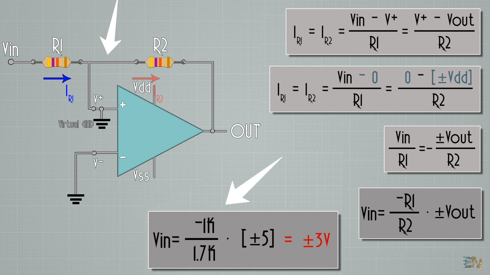
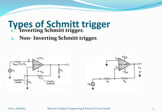
Module3 opamp as a Schmitt trigger Circuit Diagram Introduction to Schmitt Triggers A Schmitt trigger is a comparator circuit that incorporates positive feedback to prevent noise and provide hysteresis. It is used to convert analog input signals into clean digital output signals. The Schmitt trigger is named after American scientist Otto H. Schmitt who invented it in 1934. The key features of a […]
A Schmitt trigger is a comparator (not exclusively) circuit that makes use of positive feedback (small changes in the input lead to large changes in the output in the same phase) to implement hysteresis (a fancy word for delayed action) and is used to remove noise from an analog signal while converting it to a digital one. Understanding Schmitt
Schmitt Trigger Hysteresis Provides Noise Circuit Diagram
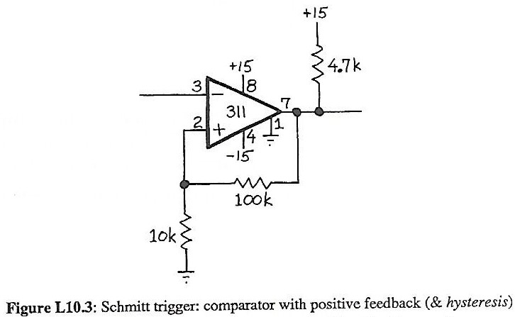
This circuit is now known as the Schmitt-trigger. Two transistors and a handful of carefully chosen resistors are enough to create the circuit. The values of the resistors define the input voltage levels where the Schmitt trigger circuit changes state. The basic Schmitt trigger circuit is shown in the next picture.
A Schmitt Trigger circuit, also known as a regenerative comparator, is widely used in electronics for its ability to handle noisy signals and produce clean, sharp transitions. Here are some of its primary applications: 1. Noise Filtering. Schmitt Triggers are used to remove noise from input signals, ensuring a clean digital output.
Working, Types and Transfer Characteristics Circuit Diagram
with the large capacitors needed for filtering. Heavily This pattern can also happen if noise is on the input. The noise can cross the threshold multiple Use Schmitt triggers to translate a sine wave into a square wave as shown in this oscillator application. Also, use Schmitt triggers to speed up a slow or