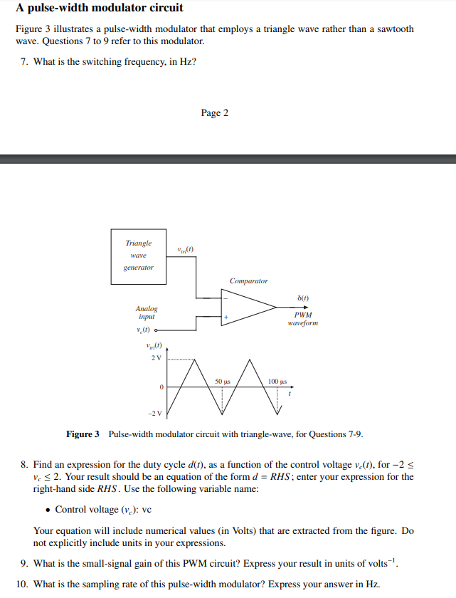
Pulse Width Modulation Circuit Diagram Pulse-width modulation, commonly known as PWM, is a modulation method that changes the pulse signal's width in electrical systems to regulate the average power supplied to a load. PWM is particularly helpful for effectively regulating the output of audio amplifiers, the speed of motors, and the brightness of light.
A PWM, or 'pulse width modulation' signal is used to reduce the electrical power supplied to an electrical device by switching the signal on and off at a high frequency. As the relative on-time of the signal increases or decreases, so does the average voltage of the signal.

Audio Signal Generators and Filters Circuit Diagram
Learn how pulse width modulation works and how to build a pulse width modulation signal generator with the 555 timer. Detailed instructions and schematics included. How to Build a Sawtooth and Triangle Wave Generator

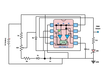
Now that we have the basics out of the way, let's build a circuit that will generate a pulse width modulation signal by using a 555 timer to switch a power MOSFET transistor. Here is the schematic: In the circuit above, we see a 555 timer configured as an astable oscillator.

Pulse Width Modulation (PWM) Circuit Diagram
The pin argument is the pin number where the pulse width modulation signal will be generated. The value argument is the analogWrite value that corresponds to the duty cycle of the pulse width modulation signal. To find the analogWrite value that will produce a pulse width modulation signal with a specific apparent voltage, use this formula: